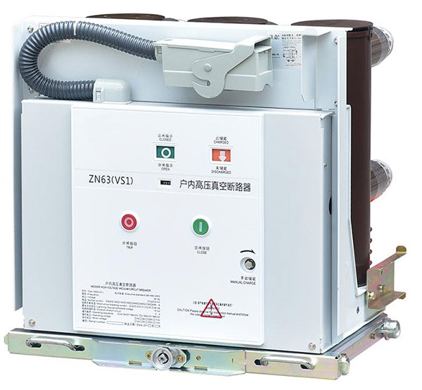

Vacuum Circuit Breaker technology has become an important switching solution for medium-voltage power distribution because it combines vacuum arc interruption with a compact mechanical structure and controlled electrical operation. When contacts separate inside a sealed vacuum interrupter, the arc is interrupted through a process fundamentally different from air, oil, or gas circuit interruption. This architecture can support fast fault clearing, reduced routine servicing of the interrupting chamber, compact switchgear construction, and repeated switching under defined operating conditions. However, the performance of a breaker cannot be evaluated by its interrupting medium alone. Rated voltage, rated current, short-circuit capability, insulation level, contact system, operating mechanism, protection relay, control voltage, installation environment, mechanical endurance, and applicable testing requirements all contribute to the final system. Understanding these relationships is essential for engineers, switchgear manufacturers, utilities, industrial facilities, renewable-energy projects, and other medium-voltage users.
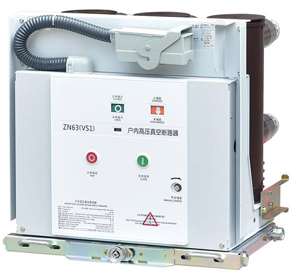
Table of Contents
Click any topic to jump directly to the section.
- 1. Why Does Medium-Voltage Switching Need Specialized Protection?
- 2. How Does Vacuum Arc Interruption Work?
- 3. What Are the Main Components of the Breaker?
- 4. How Do Rated Voltage and Current Influence Selection?
- 5. Why Are Short-Circuit Capability and Interruption Speed Important?
- 6. How Does the Operating Mechanism Affect Performance?
- 7. What Is the Difference Between Indoor and Outdoor Designs?
- 8. How Do Vacuum Breakers Compare With Other Interruption Technologies?
- 9. How Does the Breaker Work With Protection Relays and Sensors?
- 10. Which Applications Use This Switching Technology?
- 11. What Common Selection and Installation Mistakes Should Be Avoided?
- 12. How Should Testing and Standards Be Evaluated?
- 13. What Should a Professional Technical Specification Include?
- 14. Frequently Asked Questions
Why Does Medium-Voltage Switching Need Specialized Protection?
Medium-voltage electrical systems operate at voltage levels that require carefully coordinated switching and protection equipment. The switching device must not only carry normal load current but also respond correctly when the network experiences a fault.
Electrical distribution networks routinely connect transformers, motors, generators, industrial feeders, utility lines, renewable-energy sources, and other loads. Under normal conditions, current flows continuously through conductors and switching equipment. During a short circuit, however, the current can increase dramatically and generate substantial thermal and electrodynamic stress.
A circuit breaker provides a controlled method of interrupting that current. Its operation needs to be coordinated with protection relays, current transformers, voltage transformers, control circuits, and the overall protection philosophy of the electrical network.
The interruption medium is especially important. Historically, circuit breakers have used several methods for controlling the arc that forms when contacts separate. Air, oil, and various gases have all been used in different generations of equipment. Vacuum technology provides another approach in which the primary arc-interrupting process takes place inside a sealed vacuum interrupter.
The breaker can connect or disconnect a defined electrical circuit under its rated operating conditions.
When the protection system detects a fault, the breaker can open and interrupt current within its specified interrupting capability.
When integrated into an appropriate switchgear architecture, the breaker can participate in defined isolation and maintenance procedures.
Breaker operation works with sensing and protection devices to isolate faults while preserving the intended distribution structure.
The function of the breaker should therefore be considered at the system level. A high interrupting rating cannot compensate for an incorrect protection setting. A well-designed breaker cannot compensate for inadequate cable termination. A sophisticated controller cannot correct a mechanical mechanism that has not been maintained correctly.
Good switchgear engineering connects these elements. The breaker, busbar, feeder, protection relay, instrument transformers, control power, interlocks, and enclosure must all be specified around the same electrical system.
Why fault interruption is different from ordinary switching
Opening a circuit under normal load conditions and clearing a short circuit are not equivalent operations. During a fault, the current can be much larger, and the electrical energy associated with the fault is significant.
The breaker must therefore be capable of interrupting current at the voltage and system conditions for which it was designed. The interrupting process must also occur quickly enough to protect the connected equipment and maintain the intended protection coordination.
This makes interruption technology a fundamental engineering decision rather than a cosmetic product feature.
How Does Vacuum Arc Interruption Work?
The defining characteristic of vacuum interruption is the use of a sealed vacuum interrupter as the arc-extinguishing chamber. The interrupter contains fixed and moving electrical contacts enclosed within a controlled vacuum environment.
When the contacts are closed, current flows through the contact surfaces. When the operating mechanism commands the breaker to open, the moving contact separates from the fixed contact. As the contact surfaces separate, an electrical arc can form between them.
Unlike an arc in air, the vacuum interrupter does not provide a substantial gaseous medium to sustain a conventional ionized path. The interruption process is therefore governed largely by metal vapor generated from the contact material during the separation event.
Contact separation
The opening movement must be controlled precisely. Contact velocity, contact travel, contact pressure, and the mechanical relationship between the moving contact and operating mechanism all influence performance.
The contacts need enough movement to establish the required dielectric distance after current interruption. The mechanical mechanism therefore has to provide consistent travel over repeated operations.
Metal vapor behavior
During arcing, material from the contacts can form metal vapor. This vapor provides the temporary conducting medium that supports the arc. When the current approaches its natural current zero in an alternating-current circuit, the arc can extinguish and the metal vapor rapidly condenses.
The interrupter must then recover sufficient dielectric strength between the separated contacts to withstand the electrical recovery voltage.
Contact material
Contact material is a significant part of vacuum interrupter design. It needs to support current carrying, arc interruption, resistance to erosion, and dielectric recovery.
Different interrupter designs use specific contact alloys and geometries to control current distribution and magnetic effects during interruption.
Shielding
Metal vapor generated during interruption can deposit on surrounding surfaces. Shielding structures inside the interrupter help control where this material travels and help maintain the required electrical-field distribution.
| Interruption Stage | What Happens | Design Requirement |
|---|---|---|
| Closed contacts | Current flows through the contact system | Low contact resistance and reliable contact pressure |
| Contact opening | Contacts begin to separate and an arc can form | Controlled opening speed and contact geometry |
| Arcing period | Metal vapor supports electrical conduction | Controlled arc behavior and contact erosion |
| Current zero | Alternating current reaches a natural zero point | Rapid dielectric recovery |
| Post-interruption | Separated contacts withstand recovery voltage | Stable insulation between contacts |
Why the sealed interrupter matters
The vacuum interrupter is a sealed component. Its internal environment is established during manufacturing and maintained throughout its intended service life.
This differs from systems that depend on a large volume of liquid or gas as the primary interruption medium. The vacuum interrupter can be packaged into a relatively compact assembly and integrated into switchgear in several ways.
However, a sealed interrupter does not mean the entire breaker is maintenance-free. The operating mechanism, external insulation, terminals, control circuits, bearings, linkages, and switchgear interfaces still require appropriate inspection and maintenance.
Vacuum interruption should therefore be understood as one part of the breaker architecture. Its effectiveness depends on contact design, interrupter construction, mechanical movement, insulation recovery, and coordination with the protection system.
What Are the Main Components of the Breaker?
A modern medium-voltage breaker contains several functional assemblies. Each contributes to either the current path, interruption process, mechanical operation, insulation system, control interface, or installation structure.
Vacuum interrupter
The vacuum interrupter contains the fixed contact, moving contact, contact rod, internal shielding elements, and sealed enclosure. It is the part responsible for interrupting current within the vacuum environment.
Its dimensional accuracy and internal construction are critical because the contact gap, alignment, contact pressure, and dielectric geometry must remain within the intended design limits.
Operating mechanism
The operating mechanism converts stored or supplied mechanical energy into contact movement. Spring-operated mechanisms are widely used in medium-voltage applications, while electromagnetic operating systems are available in certain designs.
The mechanism must open and close the interrupter with consistent timing and travel. It also needs to maintain the required contact force in the closed position.
Insulating supports
Insulation supports physically separate energized components from the grounded enclosure and surrounding structures. They also help maintain the required clearances and mechanical stability.
Terminals and current path
Primary terminals connect the breaker to the upstream and downstream electrical network. Their design determines how the breaker interfaces with busbars, cable connections, or other switchgear components.
Position and indication system
In many switchgear installations, mechanical indicators show whether the breaker is open, closed, or in another defined position. This can be especially important for withdrawable equipment.
Control and auxiliary circuits
Auxiliary contacts, trip coils, closing coils, motor drives, position switches, and other circuits allow the breaker to communicate with protection and control equipment.
| Component | Main Function | Key Engineering Consideration |
|---|---|---|
| Vacuum interrupter | Arc interruption | Contact design, vacuum integrity, dielectric recovery |
| Operating mechanism | Contact opening and closing | Speed, travel, force, consistency, endurance |
| Insulation supports | Electrical separation and structural support | Dielectric performance and mechanical strength |
| Primary terminals | Connect breaker to the power circuit | Current capacity, connection geometry, temperature rise |
| Auxiliary contacts | Status and control feedback | Contact reliability and circuit compatibility |
| Trip and close circuits | Electrical actuation | Control voltage, timing, protection coordination |
Mechanical synchronization
Three-phase breakers need the contacts to operate in a coordinated manner. The mechanism transfers movement to the individual poles so that the phases open and close within the required timing relationship.
Excessive timing variation can influence switching performance, so mechanism adjustment and inspection are important parts of quality control and maintenance.
Why component integration matters
A high-quality interrupter cannot compensate for poor mechanism alignment. Strong insulation cannot compensate for an incorrectly designed terminal connection. An accurate relay cannot compensate for inadequate control wiring.
Reliable breaker performance therefore depends on the interaction of all these components.
How Do Rated Voltage and Current Influence Selection?
Rated voltage and current establish the basic electrical operating envelope of a breaker. They are among the first specifications engineers examine, but they are only part of a complete technical evaluation.
Rated voltage
The rated voltage must correspond to the electrical system in which the breaker will operate. The insulation system must also be designed for the relevant power-frequency and transient voltage stresses.
Medium-voltage breakers can be manufactured for different voltage classes. Product families may include equipment around 10 kV, 12 kV, 24 kV, 36 kV, or other defined ratings depending on the design and market.
The actual selection should follow the system's nominal voltage and applicable standard rather than simply selecting the next available rating.
Rated current
Rated current represents the continuous current the breaker can carry under defined conditions. Thermal performance is therefore central to the specification.
Contacts, terminals, conductors, flexible connections, busbar interfaces, and enclosure ventilation all contribute to heat generation and dissipation.
Frequency
Power frequency affects the electrical behavior of the interruption system and the associated protection and measurement equipment. Products may be specified for 50 Hz, 60 Hz, or another defined operating frequency.
Insulation level
Insulation coordination includes more than the nominal operating voltage. Equipment may need to withstand power-frequency withstand voltage and impulse conditions defined by the applicable design requirements.
| Parameter | What It Defines | Why It Matters |
|---|---|---|
| Rated voltage | Electrical system voltage class | Determines insulation and switching requirements |
| Rated current | Continuous current capability | Determines thermal and conductor requirements |
| Rated frequency | Power-system operating frequency | Ensures compatibility with the electrical network |
| Insulation level | Dielectric withstand requirements | Supports insulation coordination |
| Short-circuit rating | Fault-current interruption and withstand capability | Protects the equipment during network faults |
Temperature-rise considerations
Continuous current produces heat at electrical contacts and conductors. The temperature-rise capability therefore needs to be evaluated alongside the enclosure arrangement.
A breaker installed inside a compact metal enclosure may experience different thermal conditions from the same breaker installed in a larger ventilated arrangement. Ambient temperature and installation altitude can also affect thermal performance.
System voltage is only the starting point
Two breakers can share a similar voltage rating but differ in current rating, short-circuit capability, operating mechanism, insulation configuration, terminal arrangement, and mechanical endurance.
A professional specification should therefore avoid reducing the selection to a single number.
Why Are Short-Circuit Capability and Interruption Speed Important?
Short-circuit performance is one of the most important specifications in medium-voltage circuit breaker selection. A fault can generate very large currents and high electromechanical forces within a short period.
Short-circuit current
The available fault current is determined by the electrical network, including generators, transformers, conductors, and system impedance. A switchgear engineer normally determines this through a short-circuit study.
The breaker must have an interruption capability appropriate to the calculated fault conditions.
Breaking current
The breaker must be capable of interrupting the specified short-circuit current at the rated system voltage. The interruption process needs to maintain dielectric recovery after the current has been extinguished.
Short-time withstand
Switchgear assemblies may also be exposed to fault currents while the protection system is clearing the event. The mechanical and thermal structure must withstand the defined current for the applicable duration.
Peak withstand
The peak value of a fault current produces electrodynamic forces on conductors and structural components. Mechanical design must account for these stresses.
Interruption timing
The total fault-clearing sequence involves several stages: fault detection, relay decision, trip-signal transmission, operating mechanism movement, contact separation, arc interruption, and network recovery.
The breaker does not act independently. The complete clearing time depends on the relay, control circuitry, trip coil, mechanical mechanism, contact movement, and electrical system.
The protection relay must identify the fault and issue the trip command within its designed operating time.
The electrical path between the relay and breaker must transfer the trip command correctly.
The mechanical system must translate the electrical command into repeatable contact movement.
The interrupter must clear the current and recover the required dielectric strength.
Why interrupting medium matters
The interruption medium determines how the arc behaves during contact separation. Vacuum technology provides a controlled sealed environment and uses contact geometry and material behavior to achieve interruption.
This can allow compact interrupter dimensions and a relatively simple interrupting chamber when compared with some older interruption technologies.
However, the final breaker rating still depends on the complete design. Vacuum technology does not mean that every vacuum breaker can interrupt any arbitrary fault current.
The correct technical approach is therefore to begin with the calculated system fault level and then verify the breaker’s rated interrupting and withstand capabilities under the applicable standard.
How Does the Operating Mechanism Affect Performance?
The operating mechanism determines how quickly and consistently the breaker contacts move. Because interruption occurs during a precise sequence of mechanical events, mechanism design is central to performance.
Spring operating mechanisms
Spring mechanisms store mechanical energy before a closing or opening operation. Electrical control commands release the stored energy to move the breaker contacts.
This architecture is widely used in medium-voltage switchgear because the mechanism can provide controlled contact movement without requiring a continuous electrical supply during the entire mechanical stroke.
Electromagnetic mechanisms
Some breaker designs use electromagnetic operating systems to generate contact movement. These mechanisms can provide different operational characteristics and may be selected according to the specific breaker architecture and control requirements.
Closing operation
During closing, the mechanism must bring the contacts together with the appropriate speed and final contact force. Stable closing behavior helps reduce mechanical impact and ensures proper current conduction.
Opening operation
The opening stroke must be fast enough and consistent enough to support the intended interruption process. Contact separation distance and velocity are important because the interrupter needs to establish the correct dielectric condition following current interruption.
Energy storage
Mechanisms commonly include an energy-storage indicator or motor-operated charging system. The control system can determine whether the mechanism has sufficient energy for the next operation.
Mechanical endurance
Repeated operations create wear in springs, shafts, bearings, linkages, latches, and auxiliary switches. Mechanical endurance testing helps establish whether the mechanism can complete the specified number of operations without unacceptable deterioration.
| Mechanism Area | Required Behavior | Possible Failure Concern |
|---|---|---|
| Energy storage | Reliable preparation for operation | Incomplete charging or motor problems |
| Opening drive | Consistent rapid contact separation | Slow movement, wear, mechanical obstruction |
| Closing drive | Controlled contact engagement | Excessive impact or incomplete closing |
| Latching | Secure contact position | Incorrect latch adjustment or wear |
| Auxiliary switches | Accurate position feedback | Incorrect indication or contact degradation |
Mechanical timing matters
For a three-phase breaker, the operation of the three poles must remain within the specified timing relationship. Excessive pole-to-pole variation can affect switching behavior and should be controlled during manufacturing and maintenance.
Maintenance of the mechanism
The sealed interrupter may require limited servicing during its intended service life, but the mechanism is external and mechanical. Inspection of linkages, lubrication where specified, fasteners, springs, bearings, and auxiliary contacts remains important.
A maintenance plan should follow the manufacturer's technical instructions and the actual switching duty of the installation.
What Is the Difference Between Indoor and Outdoor Designs?
Indoor and outdoor breakers can use the same basic interruption principle while having very different mechanical and environmental requirements.
Indoor breakers
Indoor breakers are typically installed within switchgear cabinets or electrical rooms. Their surrounding environment may be more controlled, allowing compact insulation and enclosure arrangements.
Indoor designs often appear as withdrawable units or fixed installations within metal-clad switchgear. The exact arrangement depends on the panel architecture.
Outdoor breakers
Outdoor equipment must tolerate rain, humidity, temperature changes, sunlight, pollution, dust, wind, and other environmental stresses.
Outdoor products therefore require suitable enclosure sealing, external insulation, material selection, surface protection, and weather-resistant mechanisms.
Composite insulation
Outdoor breakers may use composite insulating materials such as silicone rubber or epoxy-based components depending on the product architecture. These materials can support insulation performance under changing environmental conditions when correctly designed.
Pole-mounted installations
Some outdoor distribution breakers are designed for pole mounting. This configuration can simplify integration into overhead distribution networks and allow the switching device to occupy a relatively small footprint.
Substation installations
Substation breakers may be installed on structures or within outdoor switchgear assemblies. Their connection to busbars, current transformers, voltage transformers, surge arresters, and grounding systems needs to be coordinated.
| Installation Type | Typical Environment | Main Design Focus |
|---|---|---|
| Indoor switchgear | Electrical rooms and enclosed cabinets | Compactness, compartment integration, service access |
| Outdoor distribution | Open-air networks | Weather resistance and insulation performance |
| Pole-mounted | Overhead distribution systems | Weight, mounting structure, remote operation |
| Outdoor substation | Utility and industrial substations | Environmental endurance, busbar integration, insulation coordination |
Environmental factors
Temperature, altitude, pollution, humidity, salt exposure, and ultraviolet radiation can all affect equipment selection.
For example, high altitude can influence the dielectric performance of air insulation, while severe pollution can affect external insulation surfaces. Coastal environments can increase corrosion exposure, especially around metal structures and connections.
Indoor does not mean maintenance-free
Indoor equipment is protected from direct weather, but dust, condensation, temperature cycling, and mechanical wear can still affect the mechanism and electrical connections.
Environmental protection should therefore be assessed realistically rather than assuming that indoor equipment operates in ideal conditions.
How Do Vacuum Breakers Compare With Other Interruption Technologies?
Understanding the differences between interruption technologies helps engineers make an informed technical decision. Each technology has its own electrical, mechanical, environmental, and maintenance characteristics.
Air interruption
Air circuit interruption uses air as the arc medium. Historically, air systems have been used across many voltage classes. Their design can involve arc chutes, magnetic blowout, or other methods for controlling the arc.
At medium voltage, compact vacuum interruption can offer a different physical architecture by placing the interruption process inside a sealed chamber.
Oil interruption
Oil circuit breakers use insulating oil both as an insulating medium and as part of the arc-extinguishing process. Older installations may still contain such equipment, but modern medium-voltage installations often use alternative technologies.
Oil systems require attention to oil condition, containment, leakage, contamination, and related maintenance issues.
SF6 interruption
SF6 gas has historically been used in gas-insulated and gas circuit-breaking equipment because of its electrical insulation and arc-extinguishing characteristics. However, environmental considerations have encouraged the development and adoption of alternative technologies in suitable applications.
Vacuum interruption
Vacuum interruption uses a sealed vacuum chamber. Its compact interrupting element and lack of insulating oil inside the interrupter are important characteristics of the technology.
| Technology | Arc Medium | Typical Consideration |
|---|---|---|
| Air | Air | Arc control structure and physical insulation requirements |
| Oil | Insulating oil | Oil condition, containment, maintenance |
| SF6 gas | SF6 | Gas sealing, handling, environmental considerations |
| Vacuum | Vacuum with metal-vapor arc behavior | Interrupter design, contact material, mechanism performance |
Why vacuum technology is widely used in medium voltage
Vacuum interruption can provide a compact interrupter, fast arc extinction, and a sealed interrupting environment. These characteristics fit well with indoor medium-voltage switchgear and many outdoor distribution applications.
The technology is also compatible with modern breaker mechanisms and digital protection systems.
Technology selection should remain application-specific
It is not technically sound to declare one interruption medium universally superior. The correct approach is to compare the requirements of the electrical network, available installation space, environmental conditions, operating duty, protection architecture, applicable standards, and maintenance strategy.
The appropriate technology is the one that satisfies the complete set of requirements.
How Does the Breaker Work With Protection Relays and Sensors?
A circuit breaker rarely operates alone. Its trip and closing actions are normally coordinated with a protection system that measures electrical conditions and determines when switching action is required.
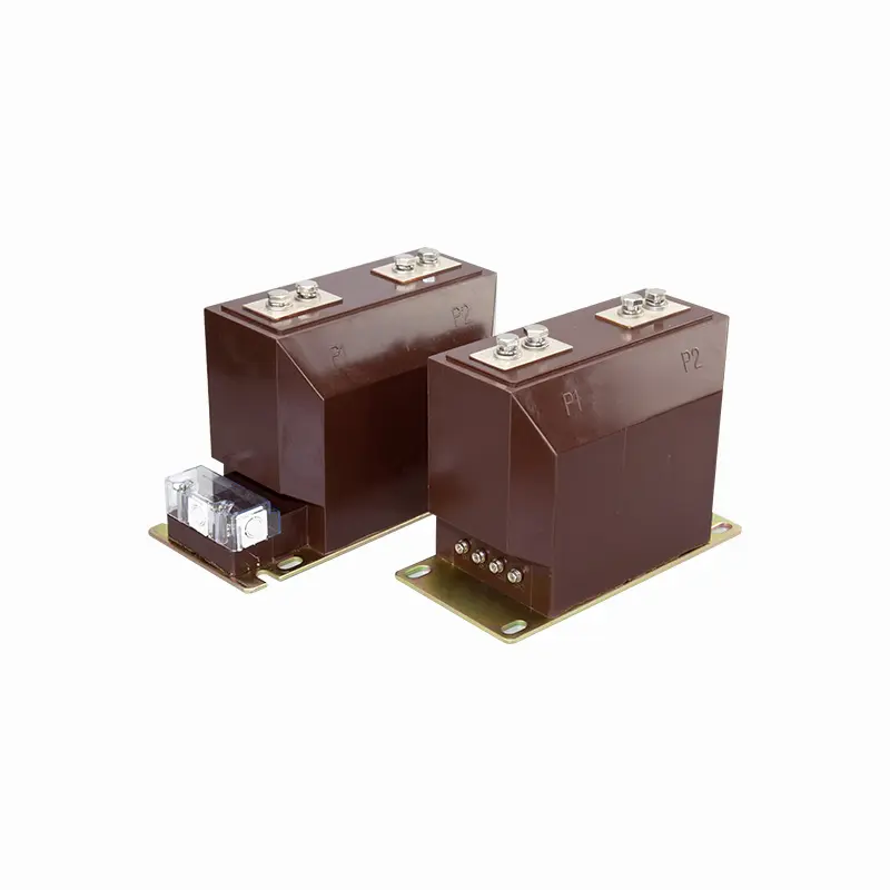
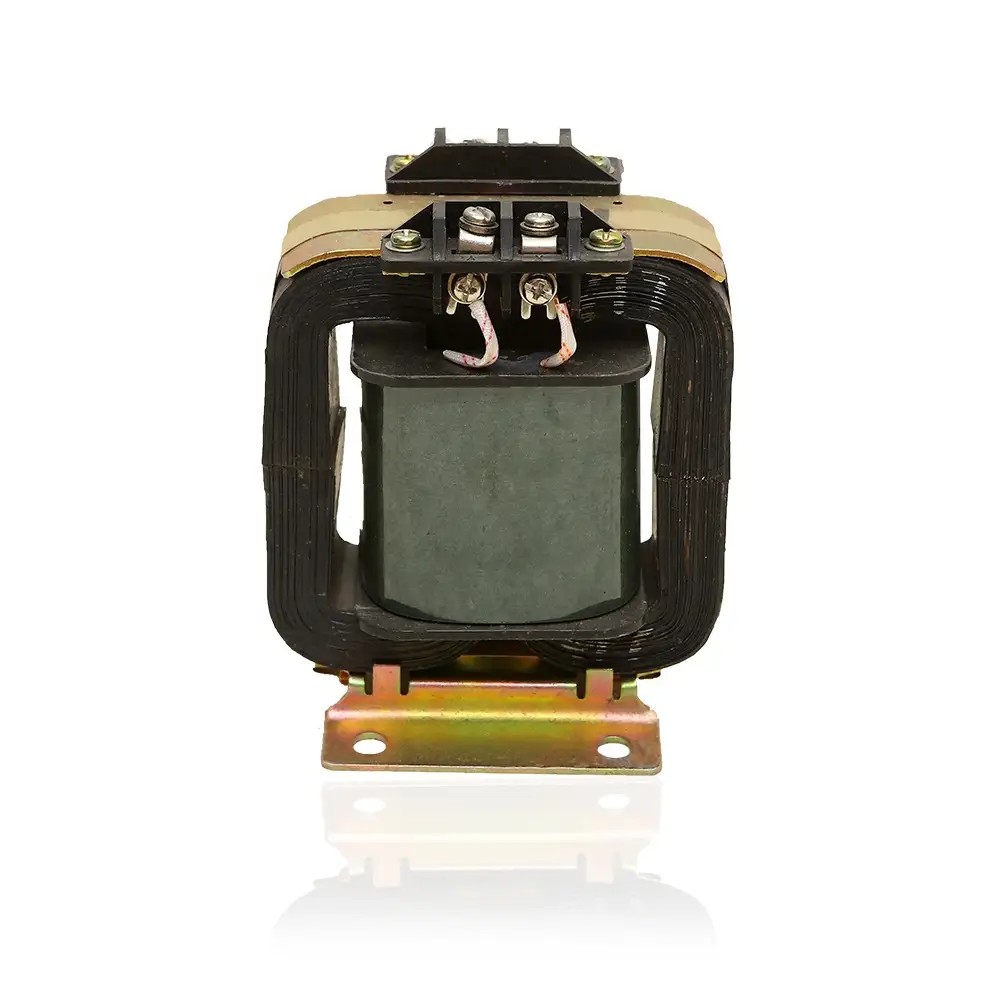
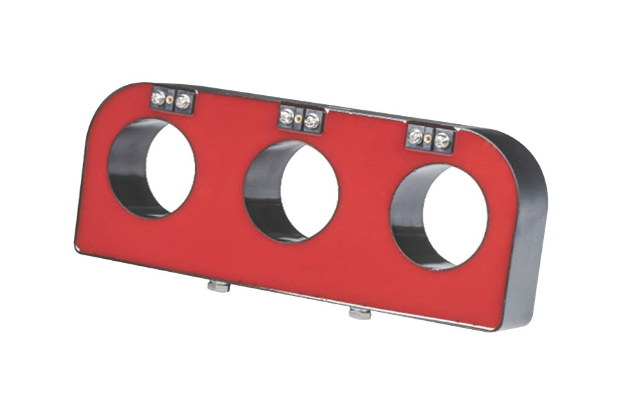
Current transformers
Current transformers provide scaled current information to protection relays and meters. Their ratios and accuracy characteristics need to match the protection scheme.
The current transformer and breaker form part of the same fault-clearing chain. If the CT configuration or wiring is incorrect, the relay may not receive the expected signal.
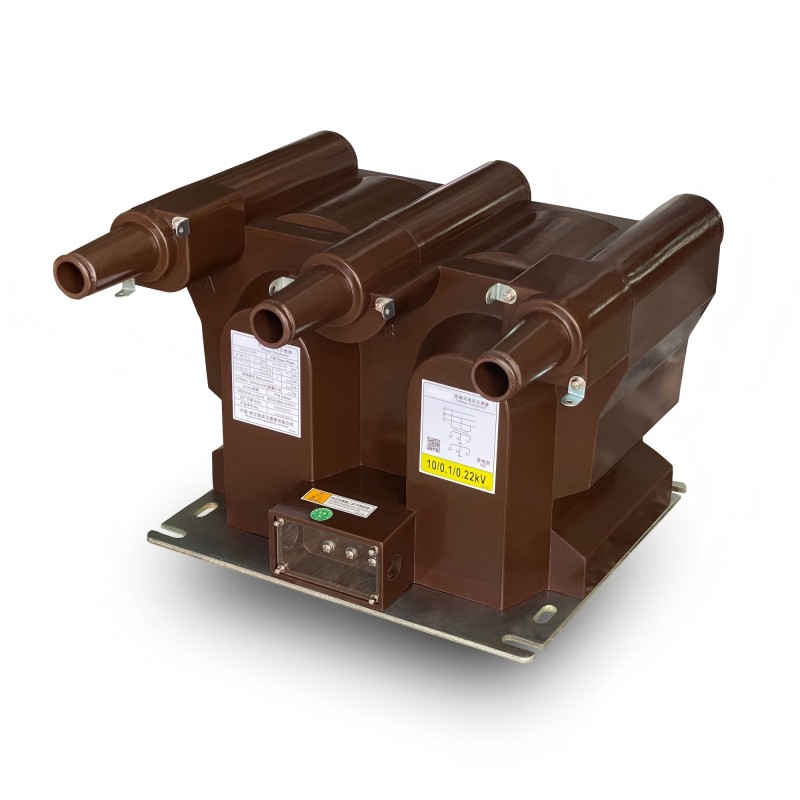
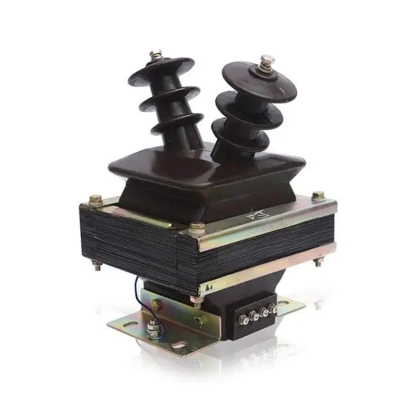
Voltage transformers
Voltage transformers can provide voltage information for protection, metering, synchronization, and control. Depending on the protection function, the relay can use voltage together with current to determine the electrical condition of the network.
Protection relays
Protection relays continuously evaluate electrical measurements. Depending on the application, functions can include overcurrent, earth fault, undervoltage, overvoltage, directional protection, motor protection, transformer protection, or other specialized functions.
Trip circuit
When the relay determines that the breaker should open, it sends a trip command through the control circuit. The trip coil actuates the mechanism, which then separates the contacts.
Closing control
Closing is also controlled. The system may include local and remote closing controls, electrical interlocks, synchronization functions, and permissive signals.
| System Element | Function | Relationship to the Breaker |
|---|---|---|
| Current transformer | Measures current | Provides protection and metering input |
| Voltage transformer | Measures voltage | Provides voltage information for protection and control |
| Protection relay | Evaluates electrical conditions | Issues trip or permissive commands |
| Trip coil | Converts electrical command into mechanical action | Initiates breaker opening |
| Control system | Supervises switching and status | Manages local, remote, and interlocked operation |
Interlocking
Interlocking is an important safety feature. Mechanical or electrical interlocks can prevent selected actions when the equipment is in an inappropriate state.
For example, a withdrawable breaker may not be permitted to move between positions while it is closed. An earthing switch may be prevented from operating while the primary circuit is energized, depending on the system architecture.
Remote monitoring
Modern electrical installations increasingly use digital communication to monitor breaker position, trip status, mechanism condition, and other parameters.
Remote information can improve operational awareness, but digital monitoring does not replace correct local safety procedures. Maintenance teams still need defined isolation, verification, grounding, and work practices.
Which Applications Use This Switching Technology?
Vacuum interruption technology is used across many medium-voltage applications because its compact form and sealed interrupter suit a wide range of distribution architectures.
Used for feeder switching, transformer connections, bus sections, and distribution protection within utility networks.
Used for medium-voltage feeders serving motors, transformers, process equipment, and internal distribution systems.
Supports collection systems, transformer connections, feeder protection, and controlled switching within solar and wind installations.
Can be applied to medium-voltage distribution networks where equipment must operate in demanding industrial environments.
Used in large buildings and campuses that receive medium-voltage electrical supplies and distribute power through transformers and feeders.
Can support electrical distribution for rail, transit, airports, and other infrastructure requiring controlled medium-voltage switching.
Utility distribution
Utility networks use medium-voltage breakers to manage feeders and sectionalize distribution circuits. A breaker can isolate a faulted feeder while allowing other parts of the network to remain energized when the network topology and protection coordination permit.
Outdoor pole-mounted configurations can be useful in overhead distribution systems, while indoor switchgear breakers are frequently integrated into substations and compact distribution assemblies.
Industrial distribution
Industrial plants can have multiple medium-voltage motors, transformers, process lines, and large electrical loads. Selective protection is particularly important because unnecessary tripping of a larger distribution section can affect several downstream circuits.
The breaker therefore needs to work with a protection scheme that reflects the plant's electrical architecture.
Transformer protection
Medium-voltage breakers can be used on the primary or secondary side of transformers depending on the network design. The protection system can incorporate overcurrent, earth-fault, temperature, and other transformer-specific functions.
Motor switching
Large motors can require medium-voltage switching and protection. Motor applications present their own challenges because starting currents can be significantly higher than normal operating current.
The breaker and protection relay must therefore be selected according to the motor's starting characteristics and protection requirements.
Renewable-energy systems
Solar and wind projects often contain multiple collection feeders and transformer interfaces. Medium-voltage breakers can be used to connect and isolate sections of the collection network and coordinate protection with the generation equipment.
Critical infrastructure
Hospitals, data centers, airports, water treatment facilities, and communication infrastructure can require highly coordinated medium-voltage distribution systems. Breaker selection in these environments is closely connected with redundancy, protection selectivity, maintenance procedures, and operational continuity.
Across all these applications, the breaker is part of a larger electrical architecture. The application determines the correct voltage, current, fault rating, protection scheme, control arrangement, environmental design, and maintenance strategy.
What Common Selection and Installation Mistakes Should Be Avoided?
Many breaker problems can be traced back to incomplete specifications or installation assumptions. The most important errors occur when engineers treat the breaker as an isolated component instead of part of a complete protection and distribution system.
- Choosing only by voltage: Rated current, fault capability, insulation, operating mechanism, and environment also need to match.
- Ignoring short-circuit calculations: The available fault current should be established before the breaker rating is finalized.
- Ignoring protection coordination: Relay settings and breaker performance must support the desired selectivity.
- Underestimating cable space: Cable terminations and bending radii can influence the practical switchgear arrangement.
- Overlooking control voltage: Trip and close circuits require appropriate auxiliary power.
- Ignoring interlocks: Operating sequences should be checked against the complete switchgear architecture.
- Skipping maintenance planning: The mechanism, terminals, control circuits, and surrounding switchgear still require inspection.
- Using incomplete documentation: Drawings, wiring diagrams, nameplate data, and test records should describe the same configuration.
The “highest rating is always better” problem
A higher rating is not automatically the correct engineering choice. The breaker still needs to fit the physical switchgear, cable arrangement, protection system, control voltage, and installation environment.
The selection should be based on calculated requirements and applicable design margins.
The “vacuum means maintenance-free” problem
The vacuum interrupter is sealed, but the breaker contains mechanical and electrical components that can experience wear. Springs, bearings, linkages, auxiliary switches, trip circuits, terminals, and control connectors all remain relevant maintenance points.
The “same breaker everywhere” problem
A clean indoor industrial room and a coastal outdoor substation represent very different environments. The same physical construction should not automatically be assumed to suit both.
The “installation later” problem
Breaker mounting, cable termination, control wiring, interlocks, and enclosure dimensions need to be considered during switchgear design. Retrofitting these details after manufacturing can be difficult.
The “document once” problem
Changes made during a project should be reflected consistently in the single-line diagram, panel drawings, wiring schematics, protection settings, bill of materials, and commissioning documents.
How Should Testing and Standards Be Evaluated?
Medium-voltage circuit breakers are safety-critical electrical devices, so testing plays a central role in confirming their performance.
IEC 62271 is an important family of standards covering high-voltage switchgear and controlgear. Different parts address different equipment types and test requirements.
Routine testing
Routine testing is performed on manufactured equipment to confirm that each production unit conforms to the applicable design requirements.
The exact test program depends on the breaker design, but can include electrical, mechanical, control, and insulation-related checks.
Type testing
Type tests validate the performance of a particular design under specified test conditions. They can address temperature rise, dielectric performance, short-circuit interruption, mechanical endurance, internal arc behavior, and other characteristics where applicable.
Dielectric testing
Dielectric tests assess whether the insulation system can withstand the specified voltage stress. This can involve power-frequency withstand and impulse-related tests depending on the applicable requirements.
Mechanical endurance testing
Mechanical endurance tests evaluate whether the operating mechanism can complete the required number of switching operations without unacceptable deterioration.
Short-circuit testing
Short-circuit type tests can evaluate the breaker’s ability to interrupt defined fault-current conditions. This is one of the most significant demonstrations of the complete interruption system.
Temperature-rise testing
Temperature-rise testing checks the thermal behavior of current-carrying components under defined current conditions. Contact resistance, conductor geometry, terminals, and enclosure design all contribute to the result.
| Test Category | Main Purpose | Typical Evidence |
|---|---|---|
| Routine test | Verify each manufactured unit | Routine inspection and test records |
| Type test | Validate the design under defined conditions | Type-test report or certificate |
| Dielectric test | Verify insulation withstand | Electrical test record |
| Mechanical endurance | Verify switching mechanism durability | Endurance test documentation |
| Short-circuit test | Verify fault interruption capability | Applicable type-test documentation |
| Temperature rise | Evaluate continuous-current thermal behavior | Thermal performance test record |
Test scope matters
A test certificate should be reviewed in context. The tested voltage, current, breaker construction, mechanism, insulation system, and accessories should correspond to the configuration being supplied.
A certificate associated with one product configuration should not automatically be assumed to cover every variation of the product family.
Factory inspection
Quality programs may also include dimensional checks, vacuum integrity verification, contact resistance measurement, mechanical timing checks, control-circuit verification, and visual inspection.
Site commissioning
After installation, the breaker and switchgear assembly need to be commissioned according to the project procedures. This can include insulation testing, contact resistance measurement, mechanical operation checks, protection relay testing, control-circuit checks, interlock verification, and functional testing.
What Should a Professional Technical Specification Include?
A professional specification should give engineers and purchasing teams enough information to select the correct breaker before the equipment reaches manufacturing or installation.
| Specification Area | Information to Define | Why It Matters |
|---|---|---|
| Rated voltage | System voltage and equipment rating | Defines electrical and insulation requirements |
| Rated current | Continuous current capability | Defines thermal and conductor requirements |
| Frequency | 50 Hz, 60 Hz, or specified system frequency | Ensures compatibility with the electrical network |
| Breaking capacity | Required short-circuit interruption rating | Determines suitability for the fault level |
| Withstand capability | Short-time and peak withstand requirements | Supports structural and thermal fault performance |
| Insulation | Insulation level and construction | Ensures dielectric suitability |
| Operating mechanism | Spring, electromagnetic, or defined alternative | Determines control and mechanical behavior |
| Control voltage | Trip, close, motor, and auxiliary circuit voltage | Ensures compatibility with the control system |
| Mounting arrangement | Fixed, withdrawable, pole-mounted, or other arrangement | Ensures physical compatibility |
| Environment | Indoor, outdoor, temperature, altitude, pollution | Matches the product to site conditions |
Start with the single-line diagram
The single-line diagram defines where the breaker sits in the electrical network. It shows incoming and outgoing feeders, transformers, motors, generators, busbars, protection zones, and other major elements.
The breaker specification should be developed from this electrical context.
Define breaker position
The specification should state whether the breaker is fixed or withdrawable and describe the relevant position and interlocking requirements.
Define primary connections
Connection geometry is particularly important for switchgear integration. Busbar spacing, cable termination, terminal orientation, and phase arrangement should correspond to the panel design.
Define auxiliary functions
Auxiliary contacts, trip coils, closing coils, undervoltage releases, motor operators, mechanical indicators, and remote-control interfaces should be clearly listed where applicable.
Define protection requirements
The protection specification should identify required relay functions, CT ratios, voltage inputs where applicable, trip logic, interlocks, and communication interfaces.
Define environmental requirements
The project should identify whether the breaker will operate indoors or outdoors and provide relevant temperature, altitude, humidity, pollution, seismic, and corrosion information where applicable.
Define testing requirements
The technical document should identify applicable standards, routine tests, type-test expectations, inspection requirements, and commissioning procedures.
- Define the electrical system: Establish voltage, frequency, network configuration, and grounding arrangement.
- Calculate system fault conditions: Determine the available short-circuit current at the breaker location.
- Define continuous load: Establish rated current and expected operating conditions.
- Choose the interruption architecture: Confirm vacuum technology and the appropriate breaker configuration.
- Define the operating mechanism: Specify the required spring or electromagnetic arrangement and operating sequence.
- Define protection: Coordinate CTs, voltage inputs, relays, trip circuits, and interlocks.
- Define physical installation: Confirm fixed or withdrawable construction, terminals, dimensions, and cable interfaces.
- Review site conditions: Confirm temperature, humidity, altitude, pollution, corrosion, and environmental exposure.
- Define testing: Confirm applicable routine, type, factory, site, and commissioning tests.
- Control documentation: Ensure all drawings, settings, specifications, and certificates describe the same final configuration.
What should buyers request before approval?
- General arrangement drawing: Confirm overall dimensions, mounting, terminal positions, and service clearances.
- Electrical schematic: Confirm trip, close, auxiliary, interlock, and control circuits.
- Nameplate data: Verify voltage, current, frequency, interrupting capacity, and relevant rated characteristics.
- Protection interface: Verify CT, VT, relay, trip, and communication interfaces.
- Test documentation: Confirm the scope of routine and type-test records applicable to the supplied design.
- Installation information: Confirm lifting, transportation, connection, commissioning, and maintenance requirements.
A detailed technical specification reduces ambiguity between engineering, purchasing, manufacturing, commissioning, and maintenance teams. It also helps prevent late-stage changes caused by missing interface information.
Frequently Asked Questions
What is the main function of a Vacuum Circuit Breaker?
It connects and disconnects medium-voltage electrical circuits and interrupts current under specified normal and fault conditions. The interruption process occurs inside a sealed vacuum interrupter.
Why is a vacuum used to interrupt an electrical arc?
The vacuum provides a controlled dielectric environment in which the arc behavior is different from air, oil, or gas interruption. After contact separation and current zero, the vacuum interrupter can recover dielectric strength rapidly under its designed conditions.
What is a vacuum interrupter?
A vacuum interrupter is a sealed chamber containing fixed and moving electrical contacts and internal shielding components. It performs the actual current interruption when the breaker opens.
What is the difference between a circuit breaker and a contactor?
A circuit breaker is designed to interrupt fault currents within its rated capability and to provide protection functions. A contactor is generally designed for frequent switching of loads under defined operating conditions and is not normally intended to perform the same fault-clearing role as a circuit breaker.
What voltage levels can vacuum interruption technology serve?
Vacuum interruption is widely used in medium-voltage equipment. Specific products can be designed for voltage classes such as 10 kV, 12 kV, 24 kV, 36 kV, 40.5 kV, and other defined ratings depending on the manufacturer's design and applicable standard.
Why is short-circuit breaking capacity important?
A fault can produce very high current. The breaker must be able to interrupt the specified fault current at the system voltage without unacceptable failure. The required rating should be based on the actual network short-circuit calculation.
What is the role of the operating mechanism?
The operating mechanism provides the mechanical movement required to open and close the contacts. It controls contact travel, speed, force, and timing and therefore has a direct influence on interruption and closing performance.
Are spring mechanisms commonly used?
Yes. Spring-operated mechanisms are widely used in medium-voltage breakers. They store mechanical energy and release it to perform the opening or closing operation when commanded.
Can electromagnetic mechanisms also be used?
Yes. Certain breaker designs use electromagnetic operating mechanisms. The choice depends on the breaker architecture, control requirements, operating sequence, and project specification.
Are vacuum breakers maintenance-free?
No. The vacuum interrupter is sealed, which limits maintenance inside the interrupting chamber, but the complete breaker still contains mechanical mechanisms, terminals, auxiliary contacts, control circuits, insulation structures, and other components that require appropriate inspection and service.
What maintenance does the operating mechanism require?
Maintenance can include inspection of mechanical linkages, springs, bearings, latches, fasteners, auxiliary switches, control wiring, and lubrication points where specified. The exact procedure should follow the manufacturer's maintenance documentation and the equipment's operating duty.
What is the difference between indoor and outdoor vacuum breakers?
Indoor products are normally integrated into protected switchgear or electrical rooms, while outdoor products are designed to withstand rain, temperature changes, sunlight, pollution, and other environmental conditions. The electrical interruption principle can be similar, but the enclosure and insulation requirements differ.
What is a withdrawable breaker?
A withdrawable breaker can move between defined mechanical positions in the switchgear, such as connected, test, and isolated positions, according to the equipment design. This arrangement can support maintenance and testing procedures while preserving defined interlocking functions.
How does the breaker work with a protection relay?
The relay receives electrical measurements from current transformers and, where applicable, voltage transformers. When the relay identifies a defined abnormal condition, it sends a trip signal to the breaker. The trip coil then actuates the mechanism to open the contacts.
Why are current transformers important?
Current transformers provide scaled current signals for protection and measurement. Their ratio, accuracy, burden, and connection arrangement need to be coordinated with the protection relay and the overall electrical system.
Why are voltage transformers sometimes used with a breaker?
Voltage transformers provide scaled voltage signals for measurement, protection, synchronization, and control. Depending on the application, the protection relay can use voltage information together with current information to determine whether a fault or abnormal operating state exists.
What is the purpose of interlocking?
Interlocking helps prevent defined unsafe operating sequences. Depending on the switchgear design, it can restrict breaker movement, earthing-switch operation, or closing actions until required conditions are satisfied.
What standards are commonly associated with medium-voltage breakers?
IEC 62271 is an important family of standards covering high-voltage switchgear and controlgear. The applicable part depends on the equipment type and design. National and regional requirements can also apply.
What is the difference between routine testing and type testing?
Routine testing is performed on manufactured units to verify conformity with the relevant production requirements. Type testing evaluates the performance of a design under specified test conditions and is generally performed as part of design validation.
What technical information should be provided when selecting a breaker?
Important information includes system voltage, rated current, frequency, short-circuit level, insulation requirements, installation location, fixed or withdrawable construction, control voltage, protection functions, auxiliary contacts, terminal arrangement, environmental conditions, and applicable standards and tests.
Can the breaker be customized for a particular switchgear cabinet?
Depending on the product family, project-specific requirements can include mounting dimensions, terminal arrangement, control voltage, auxiliary circuits, mechanism configuration, protection interfaces, and other defined technical parameters. Customized configurations should be controlled through approved engineering documents.
Which industries commonly use vacuum interruption technology?
Applications include utility distribution, substations, industrial plants, mining, renewable-energy facilities, commercial buildings, transport infrastructure, water treatment, and other medium-voltage electrical installations.
Why should the breaker and switchgear be specified together?
The breaker has to fit the switchgear mechanically and electrically. Busbar interfaces, cable connections, control circuits, interlocks, protection systems, service clearances, and environmental requirements all depend on the complete panel configuration.
How Can Better Breaker Selection Strengthen Medium-Voltage Power Distribution?
Medium-voltage switching equipment is one of the key interfaces between an electrical network and the protection system responsible for controlling abnormal conditions. A breaker must carry continuous load current, operate reliably, interrupt defined fault currents, withstand electrical and mechanical stress, and communicate accurately with the surrounding control architecture.
Vacuum interruption provides a practical foundation for many of these requirements. The sealed interrupter creates a controlled environment for arc extinction and can support compact switchgear construction. However, the vacuum itself is only one element of the complete product.
The contact system, shielding arrangement, insulation supports, operating mechanism, terminals, control circuits, auxiliary contacts, and enclosure must all work together. Mechanical consistency is especially important because the opening and closing movement determines the conditions under which the interrupter performs its function.
Electrical selection is equally important. Rated voltage and current provide the starting point, but short-circuit current, insulation level, frequency, temperature rise, and environmental conditions determine whether a particular configuration fits the actual network.
The protection system adds another layer. Current transformers, voltage transformers, relays, trip coils, control power, communication interfaces, and interlocks create the chain through which the electrical system detects a fault and responds to it.
Application also matters. Utility substations, industrial facilities, renewable-energy networks, mining sites, commercial buildings, transport infrastructure, and critical facilities do not necessarily have the same electrical or environmental requirements.
Testing and documentation provide the final technical foundation. Routine tests, type tests, dielectric evaluations, mechanical endurance tests, short-circuit tests, temperature-rise evaluations, installation checks, and commissioning procedures should all correspond to the final equipment configuration.
A properly specified Vacuum Circuit Breaker is therefore not simply a switching component. It is part of an integrated medium-voltage protection architecture that connects electrical interruption, mechanical operation, sensing, control, and system safety.
Need a Medium-Voltage Breaker Configuration for Your Project?
Comewill supports medium-voltage switching solutions for utility, industrial, renewable-energy, commercial, and infrastructure applications, with configurations covering electrical ratings, operating mechanisms, protection interfaces, mounting arrangements, and project-specific technical requirements. For application details and technical discussions, contact us.