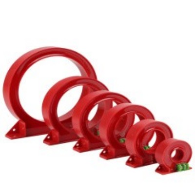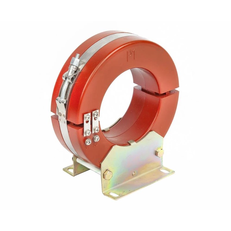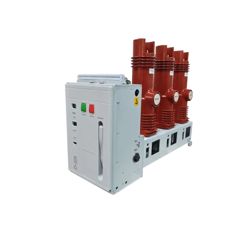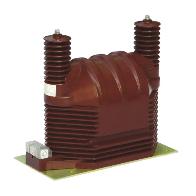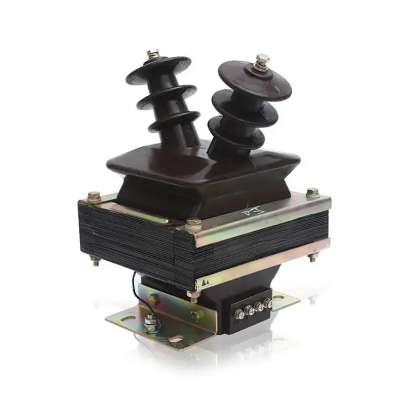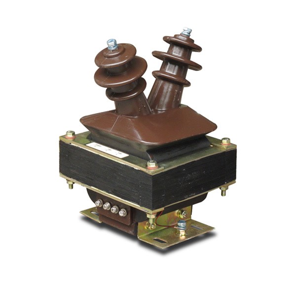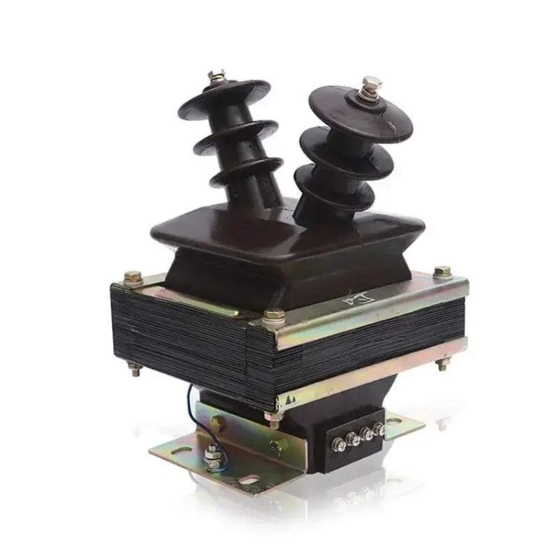

A Voltage Transformer is an important instrument-transformer technology used to reduce high primary voltage to a proportional secondary voltage suitable for measurement, metering, protection, and control. Unlike a power transformer, which is intended for energy transfer between electrical networks, an instrument transformer is designed to provide an accurate signal to meters, relays, monitoring equipment, and control systems. The correct selection depends on primary-system voltage, secondary voltage, frequency, accuracy requirements, burden, insulation, phase arrangement, winding configuration, installation location, environmental exposure, and the intended protection or measurement function. Electromagnetic, capacitive, and electronic technologies provide different approaches to obtaining proportional voltage signals. Indoor and outdoor designs also address different environmental conditions. A complete technical evaluation therefore needs to consider electrical performance, insulation, construction, accessories, protection, installation, and maintenance as one coordinated system.
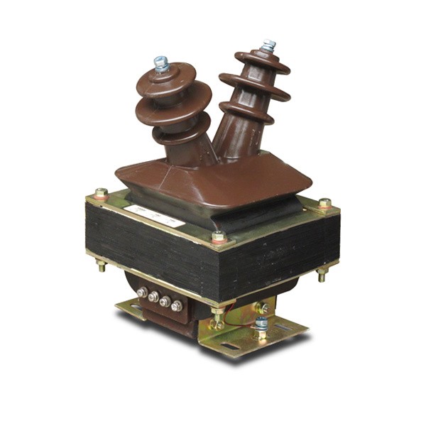
Table of Contents
Click any topic to jump directly to the section.
- 1. Why Is Voltage Measurement Important in Power Systems?
- 2. How Does an Instrument Voltage Transformer Work?
- 3. What Are the Main Types and Configurations?
- 4. How Do Accuracy and Burden Affect Selection?
- 5. Why Are Insulation and Electrical Isolation Essential?
- 6. How Do Protection and Measurement Applications Differ?
- 7. What Is the Difference Between Electromagnetic and Capacitive Designs?
- 8. How Do Indoor and Outdoor Designs Address Different Conditions?
- 9. How Do Single-Phase and Three-Phase Applications Differ?
- 10. How Should Fuses, Secondary Grounding, and Safety Be Considered?
- 11. Which Applications Use Instrument Voltage Measurement?
- 12. What Common Selection Mistakes Should Be Avoided?
- 13. What Should a Professional Technical Specification Include?
- 14. Frequently Asked Questions
Why Is Voltage Measurement Important in Power Systems?
Electrical networks cannot be controlled safely and accurately without reliable information about voltage. Operators, protection relays, meters, automation systems, and monitoring equipment all depend on measurement signals that represent the condition of the primary electrical circuit.
Directly connecting conventional meters or low-voltage control equipment to a medium- or high-voltage circuit would be impractical and potentially dangerous. Instrument transformers solve this problem by creating a proportional secondary signal that represents the primary voltage while providing electrical separation between the high-voltage circuit and the secondary measuring circuit.
This separation has several practical advantages. The measurement equipment can be designed around a standardized secondary voltage instead of being exposed directly to the primary system. Protection relays can process a manageable signal. Energy meters can perform their measurement functions. Operators can obtain information about the electrical network without bringing the primary voltage directly into the control panel.
Provides a proportional voltage signal for meters and monitoring devices.
Supplies voltage information to protective relays that evaluate abnormal system conditions.
Separates the secondary measurement circuit from the high-voltage primary network.
Provides an electrical signal that can support automation, switching logic, synchronization, and other control functions.
Voltage information is particularly important in systems where the electrical condition changes continuously. Substations, industrial distribution systems, transformer feeders, renewable-energy networks, and complex utility systems all require reliable information about system voltage.
Measurement also supports troubleshooting. If the observed secondary signal changes unexpectedly, engineers can investigate whether the cause is related to the primary system, the instrument transformer, wiring, protection circuit, or another part of the measurement chain.
A reliable measurement chain therefore begins with a properly selected instrument transformer. Accuracy, insulation, connection configuration, secondary burden, environmental conditions, and protection requirements all need to be considered together.
How Does an Instrument Voltage Transformer Work?
An electromagnetic instrument voltage transformer works through electromagnetic induction. The primary winding is connected to the high-voltage circuit, while the secondary winding provides a proportional lower voltage to connected measuring or protection equipment.
The basic relationship is determined by the ratio of primary turns to secondary turns. When the primary winding is energized, magnetic flux is established in the core. This flux induces a voltage in the secondary winding that corresponds proportionally to the primary voltage within the transformer's designed operating range.
Primary winding
The primary winding connects to the high-voltage circuit. Its insulation system is therefore designed to withstand the electrical stresses associated with the primary network.
Depending on the product architecture, the primary winding can have different physical constructions. Some designs use a conventional winding arrangement, while others integrate the winding into an encapsulated insulation structure.
Secondary winding
The secondary winding provides the reduced voltage signal to meters, relays, and other equipment. Its output is designed to remain proportional to the primary voltage under specified electrical conditions.
Magnetic core
The core provides the magnetic path required for electromagnetic induction. Core construction and magnetic characteristics influence accuracy, excitation behavior, losses, and the transformer's ability to provide a stable secondary signal.
Insulation system
The insulation system separates the high-voltage primary winding from the secondary winding, enclosure, and surrounding structure. Depending on the product design, this can involve dry insulation, epoxy-resin casting, oil insulation, gas insulation, or other dielectric arrangements.
| Component | Primary Function | Key Design Consideration |
|---|---|---|
| Primary winding | Connects to the high-voltage circuit | Primary voltage and insulation requirements |
| Secondary winding | Provides the reduced measurement signal | Secondary voltage, accuracy, burden |
| Magnetic core | Provides the magnetic path | Core material and excitation characteristics |
| Insulation system | Maintains electrical separation | Voltage stress, environment, mechanical stability |
| Enclosure or housing | Provides mechanical and environmental protection | Installation location and exposure conditions |
Secondary signal quality
A useful secondary signal must accurately represent the primary voltage while connected equipment draws its specified load. If the measurement circuit places excessive burden on the secondary, the voltage ratio and accuracy can be affected.
This is why the transformer, wiring, terminals, meters, relays, and other secondary equipment should be evaluated as one circuit.
The working principle may be simple in concept, but achieving stable accuracy under real operating conditions requires careful design of the core, windings, insulation, connections, and mechanical structure.
What Are the Main Types and Configurations?
Instrument voltage transformers can be classified according to installation, phase arrangement, winding configuration, insulation technology, and operating principle. These categories help engineers narrow the selection according to system requirements.
Indoor configurations
Indoor units are intended for installation inside switchgear, substations, electrical rooms, or other protected environments. Their enclosure and insulation design can be optimized around a controlled indoor environment.
Epoxy-resin cast designs are common in compact indoor medium-voltage applications because the solid insulation can create a sealed structure while keeping the physical assembly relatively compact.
Outdoor configurations
Outdoor units face direct exposure to rain, humidity, temperature changes, sunlight, dust, pollution, and other environmental conditions. Their housing and insulation arrangement therefore need to address outdoor service.
Single-phase configurations
Single-phase designs are commonly used where each phase is measured separately or where the application requires a defined phase-to-ground or phase-to-phase measurement arrangement.
Three-phase configurations
Three-phase arrangements can provide coordinated voltage measurement for three-phase electrical networks. The exact connection depends on the system neutral configuration and the protection or metering function.
Two-winding and three-winding configurations
A two-winding design contains one primary and one secondary winding. A three-winding design adds an auxiliary secondary winding that may support a separate protection or grounding-related function, depending on the electrical scheme.
Dry-type and cast-resin systems
Dry-type systems use solid or dry insulation without liquid dielectric. Epoxy-resin cast construction can fully encapsulate selected components, providing mechanical stability and resistance to moisture and contamination.
Oil-immersed designs
Oil-immersed configurations use insulating oil as part of the dielectric and thermal system. These designs require appropriate tank construction, sealing, oil management, and maintenance procedures.
Inflatable or gas-insulated configurations
Gas-insulated designs can be used where enclosed dielectric systems are appropriate. Their selection should include consideration of enclosure sealing, gas properties, pressure management, service procedures, and environmental requirements.
Capacitive and electronic technologies
Not every voltage measurement system relies on a conventional electromagnetic transformer. Capacitive voltage transformers use a capacitive divider in combination with an electromagnetic section, while electronic voltage sensors use sensing and signal-conversion methods to produce a proportional electrical output.
| Classification | Typical Options | Selection Focus |
|---|---|---|
| Installation | Indoor, outdoor | Environmental exposure and enclosure design |
| Phase | Single-phase, three-phase | Network configuration and measurement scheme |
| Winding | Two-winding, three-winding | Metering, protection, auxiliary functions |
| Insulation | Dry, cast-resin, oil, gas | Voltage class, environment, maintenance |
| Working principle | Electromagnetic, capacitive, electronic | Voltage level, accuracy, system architecture |
The selection should begin with the application and network requirements, not simply the product category. Different configurations can satisfy similar measurement functions while providing different installation and maintenance characteristics.
How Do Accuracy and Burden Affect Selection?
Accuracy is one of the most important technical considerations because the secondary signal may be used for energy measurement, system monitoring, protection, control, or several functions at the same time.
Accuracy class
The accuracy class describes the allowable measurement error under defined conditions. Different applications may have different accuracy requirements.
Measurement circuits used for metering can require a tighter accuracy than applications where the transformer primarily provides a protection signal. The correct class therefore depends on what the secondary circuit needs to accomplish.
Rated burden
Burden refers to the load connected to the secondary winding. This includes meters, relay inputs, transducers, wiring, terminal blocks, and other connected devices.
If the secondary circuit's actual burden differs significantly from the conditions for which the transformer was specified, the accuracy and output behavior can change.
Ratio accuracy
The transformation ratio needs to remain within the specified tolerance. A mismatch between the intended ratio and the actual ratio can influence both measurement values and protection decisions.
Phase displacement
In measurement systems involving power calculations, phase relationships matter. Small errors in phase displacement can affect the accuracy of calculations derived from voltage and current signals.
| Parameter | What It Describes | Why It Matters |
|---|---|---|
| Accuracy class | Measurement accuracy under defined conditions | Determines suitability for metering or protection |
| Rated burden | Secondary circuit load | Influences secondary voltage and accuracy |
| Transformation ratio | Primary-to-secondary voltage relationship | Ensures measurement represents the primary system correctly |
| Phase displacement | Angular relationship between primary and secondary voltage | Can affect power and protection calculations |
Metering versus protection requirements
Measurement-oriented applications generally focus on maintaining accurate proportional output across the relevant operating range. Protection-oriented applications may place greater emphasis on the transformer's behavior during abnormal system conditions and the ability of the secondary signal to support relay operation.
This distinction should be reflected in the technical specification. A product selected only according to nominal voltage can be unsuitable if its accuracy and burden characteristics do not match the connected circuit.
Why Are Insulation and Electrical Isolation Essential?
Electrical isolation is one of the central reasons instrument voltage transformers are used. The primary circuit can operate at a voltage far above the safe operating range of conventional measurement and control devices, so the insulation system must create a reliable separation between primary and secondary circuits.
Primary-to-secondary isolation
The insulation system needs to withstand the electrical stress associated with the rated primary voltage and defined transient conditions. The design includes insulation materials, creepage distances, clearances, winding arrangement, encapsulation, terminals, and enclosure geometry.
Solid insulation
Cast-resin designs can encapsulate the windings and other electrical components. This approach can provide a compact and mechanically stable structure while reducing direct exposure of internal insulation surfaces to moisture or contamination.
Oil insulation
Oil provides both dielectric insulation and heat-transfer characteristics. Oil-filled designs need appropriate containment and sealing to maintain the intended internal environment.
Gas insulation
Gas-insulated assemblies use an enclosed dielectric medium. The enclosure must maintain its integrity, and service procedures must account for the dielectric medium and the equipment's pressure or sealing arrangement.
Creepage and clearance
Clearance refers to the shortest distance through air between conductive parts, while creepage relates to the distance along an insulating surface. Both are important in the design of medium- and high-voltage equipment.
Environmental pollution can increase the importance of creepage distance because contamination on an insulating surface can create a path for leakage current.
The insulation must withstand the specified electrical stress without breakdown.
The insulation system should maintain its function under the expected humidity, contamination, and temperature conditions.
Windings and insulation need to remain stable during transport, installation, and normal operation.
The low-voltage measurement circuit must remain properly separated from the primary network.
Insulation is therefore not a single material choice. It is a complete engineering system involving geometry, materials, manufacturing quality, environmental exposure, and electrical coordination.
For buyers, this means the insulation description should be specific. Terms such as dry type, cast resin, oil immersed, or gas insulated provide a starting point, but the technical specification should also explain the intended voltage class and installation conditions.
How Do Protection and Measurement Applications Differ?
The same primary voltage circuit may provide signals to both measurement and protection systems, but the requirements of these two functions are not identical.
Measurement applications
Measurement systems need a stable proportional voltage so that meters and monitoring devices can accurately represent the primary system. Accuracy across the normal operating range is therefore especially important.
Applications can include voltage meters, energy meters, power-quality equipment, supervisory systems, and other monitoring devices.
Protection applications
Protection relays use electrical signals to identify abnormal conditions. Voltage information may contribute to undervoltage, overvoltage, directional, distance, synchronizing, or other protection functions depending on the network architecture.
The transformer must provide an appropriate signal under the conditions relevant to the protection scheme.
Combined applications
Some systems use separate secondary windings for different functions. One winding can support measurement while another is assigned to protection.
This arrangement can help isolate the requirements of different circuits and reduce interaction between measurement loads and protection inputs.
| Application | Typical Secondary Function | Main Design Priority |
|---|---|---|
| Voltage metering | Accurate proportional voltage | Specified accuracy and burden |
| Energy measurement | Voltage signal for electrical calculations | Ratio accuracy and phase performance |
| Relay protection | Voltage input for fault logic | Protection performance and suitable secondary behavior |
| Control systems | Voltage feedback or synchronization | Stable and correctly scaled signal |
| Monitoring | System condition data | Reliable signal quality and integration |
Auxiliary secondary windings
Three-winding products can provide an additional secondary output for specialized applications. The exact purpose depends on the system configuration and protection scheme.
This is one reason technical drawings are valuable. A complete winding diagram reveals more useful information than a general statement that the product has multiple outputs.
Secondary circuit design
The connected circuit should be considered in its entirety. Long cable runs, terminal blocks, meters, relays, transducers, and other equipment all contribute to the actual secondary burden and signal behavior.
What Is the Difference Between Electromagnetic and Capacitive Designs?
Different voltage-measurement technologies solve the same basic problem in different ways. Understanding their operating principles helps engineers match the equipment to the network and application.
Electromagnetic technology
The conventional electromagnetic design uses primary and secondary windings coupled through a magnetic core. It is familiar, well established, and suitable for many medium-voltage measurement and protection applications.
Its selection involves the primary voltage, secondary voltage, frequency, accuracy, burden, insulation, and winding configuration.
Capacitive voltage transformer technology
A capacitive voltage transformer uses a capacitive divider to reduce the primary voltage before an electromagnetic transformer section processes the signal. This architecture can be useful at higher voltage levels and can also support certain communication-related applications depending on its construction.
The capacitive components form part of the overall voltage division network, so insulation, frequency behavior, compensation, and system connection need to be considered carefully.
Electronic voltage sensing
Electronic voltage transformers or sensors can use sensing elements and electronic converters to produce a proportional output. These technologies can support compact system architectures and integration with digital protection or monitoring systems.
The output interface, power requirements, signal protocol, accuracy, environmental limits, and compatibility with the downstream system need to be specified clearly.
| Technology | Basic Principle | Typical Selection Consideration |
|---|---|---|
| Electromagnetic | Primary and secondary windings with magnetic coupling | Ratio, accuracy, burden, insulation, core design |
| Capacitive | Capacitive voltage division with transformer conversion | Voltage class, frequency behavior, compensation, system integration |
| Electronic | Sensor and electronic signal conversion | Output type, electronics, communication, accuracy, environmental limits |
Why technology choice matters
The right technology depends on the network rather than on a generic preference. A compact indoor medium-voltage switchgear application may have different requirements from a high-voltage outdoor substation.
Space, environmental exposure, insulation requirements, maintenance strategy, measurement accuracy, communication architecture, and the intended protection function all influence the appropriate technology.
How Do Indoor and Outdoor Designs Address Different Conditions?
Installation environment affects the enclosure, insulation, surface protection, terminals, sealing, mechanical structure, and maintenance approach.
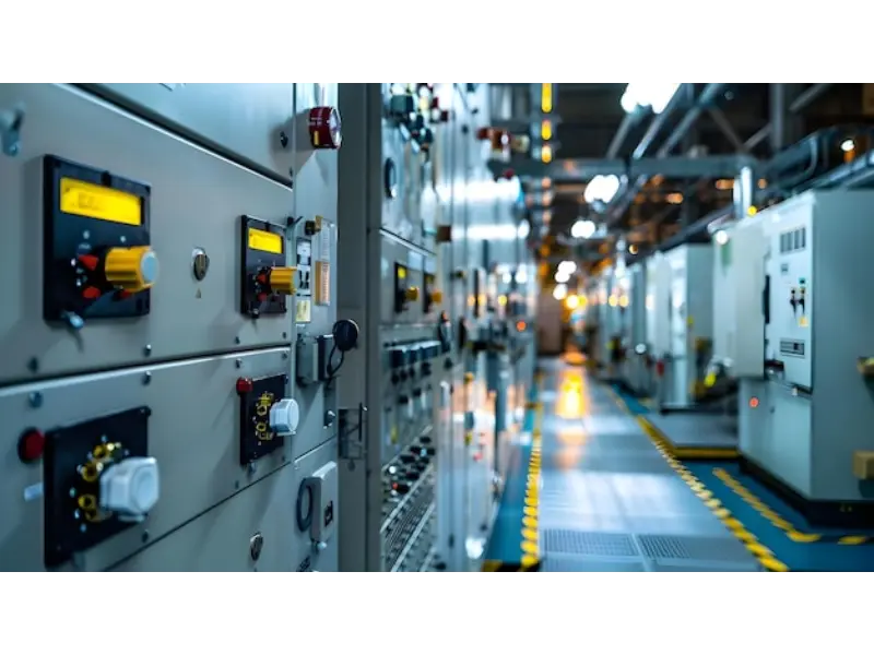
Indoor electrical rooms
Indoor equipment typically benefits from controlled temperature and humidity compared with outdoor installations. This can allow compact insulation and enclosure designs, provided the room itself maintains suitable environmental conditions.
Indoor medium-voltage equipment may also need to fit inside standardized switchgear compartments. Compact dimensions, mounting arrangement, cable access, and terminal orientation therefore become important.
Outdoor substations
Outdoor equipment must withstand weather exposure. Rain, humidity, ultraviolet radiation, pollution, dust, wind, and temperature cycling can all affect the equipment.
Housing materials, sealing, sheds, creepage distance, surface treatment, and terminal design should reflect those conditions.
Pollution and contamination
Industrial sites and coastal areas can present contamination conditions that are significantly more demanding than clean indoor environments.
Insulation surfaces need to maintain appropriate performance when exposed to moisture and contamination. The physical arrangement of insulators and protective sheds may therefore be important.
Temperature variation
Outdoor equipment may experience substantial daily and seasonal temperature changes. These changes can create mechanical expansion and contraction as well as condensation risks.
| Condition | Potential Effect | Design Response |
|---|---|---|
| Humidity | Condensation and insulation stress | Appropriate enclosure and anti-condensation design |
| Rain | Moisture exposure | Suitable sealing, housing, and terminal protection |
| Pollution | Surface contamination and leakage paths | Appropriate creepage and insulation arrangement |
| UV exposure | Material aging | Suitable outdoor materials and surface treatment |
| Temperature cycling | Condensation and mechanical stress | Material selection and environmental evaluation |
Installation position inside switchgear
When installed inside a medium-voltage switchgear assembly, the transformer must fit the available compartment while maintaining required clearances and connections.
Cable routes, primary terminals, secondary wiring, inspection access, and adjacent equipment should be reviewed during the panel design stage.
How Do Single-Phase and Three-Phase Applications Differ?
Phase arrangement is an important part of system design because the transformer must match the way voltage is measured within the electrical network.
Single-phase measurement
Single-phase units can be used to measure an individual phase or a defined phase-to-ground or phase-to-phase voltage depending on the wiring scheme.
This arrangement is common when separate phase measurements are required or when the protection design uses specific voltage references.
Three-phase measurement
Three-phase systems require coordinated measurement of the three phase voltages. The transformer configuration depends on whether the system is grounded, ungrounded, or uses another neutral arrangement.
Connection diagrams are therefore essential because two systems with similar voltage ratings can require different transformer wiring.
Winding arrangements
Double-winding designs provide one main secondary circuit. Three-winding designs add another secondary winding that can be assigned to a separate function.
The additional winding can be useful when metering and protection circuits need distinct outputs.
Connection schemes
Possible arrangements can include phase-to-phase measurement, phase-to-ground measurement, open-delta-related arrangements, or other system-specific configurations. The correct scheme depends on the electrical network.
Useful where a defined individual phase voltage must be measured or monitored.
Suitable for coordinated voltage measurement in three-phase electrical networks.
Provides one primary and one secondary circuit for the intended measurement or control function.
Adds an auxiliary secondary output for an independent protection or specialized circuit.
Why the wiring diagram matters
A product name alone cannot always communicate the complete phase and winding configuration. A wiring diagram shows which terminals belong to each winding and how the transformer should connect to the external system.
This is particularly important for customized installations where the secondary circuit is connected to several different devices.
How Should Fuses, Secondary Grounding, and Safety Be Considered?
Instrument voltage transformers are connected directly to high-voltage circuits, so their protection and secondary wiring require careful engineering.
Primary fuses
Some transformer configurations include high-voltage fuses or are installed with external protective fuses. Their purpose is to limit the consequences of internal faults and protect the surrounding electrical system according to the designed protection scheme.
The fuse rating and coordination should match the transformer and the network rather than being selected independently.
Secondary grounding
The secondary circuit normally uses a defined grounding arrangement to establish a known reference and reduce the risk associated with accidental secondary-to-primary potential transfer.
The exact grounding method should follow the transformer design, electrical code, protection philosophy, and local installation requirements.
Terminal identification
Primary and secondary terminals should be clearly identified. Incorrect wiring can affect measurement polarity, protection functions, and the safety of personnel working on the secondary circuit.
Interconnection safety
Secondary circuits should be routed and protected so that they do not become damaged by vibration, sharp edges, heat, moisture, or mechanical interference.
Maintenance isolation
Maintenance personnel need a clearly defined procedure for isolating the associated primary equipment and proving the relevant conditions before working on the secondary circuit or surrounding equipment.
- Confirm primary protection: Verify the fuse or protective-device arrangement defined for the transformer.
- Verify secondary grounding: Follow the approved grounding and bonding arrangement.
- Identify every terminal: Match wiring with the approved schematic and transformer nameplate.
- Protect secondary wiring: Keep cables away from mechanical and environmental hazards.
- Follow isolation procedures: Maintenance should be performed only under the defined electrical safety procedure.
Safety is therefore a system responsibility. Product construction, installation, protection, grounding, documentation, and operating procedures all have to support one another.
Which Applications Use Instrument Voltage Measurement?
Voltage measurement is required in many parts of modern electrical infrastructure. The exact transformer configuration depends on the network voltage, physical environment, accuracy requirement, protection scheme, and type of connected equipment.
Supports voltage measurement, protection, control, metering, and monitoring across incoming and outgoing circuits.
Provides voltage signals for motors, transformers, feeders, protection systems, and electrical monitoring.
Supports voltage monitoring and protection within solar, wind, and other generation-related networks.
Provides measurement signals for medium-voltage electrical distribution systems serving large facilities.
Fits into medium-voltage assemblies where measurement and relay protection need a controlled voltage signal.
Provides proportional voltage information for monitoring, control, synchronization, and electrical-system automation.
Substation applications
Substations frequently require voltage signals for protection relays, metering, control systems, and operator monitoring. A transformer can therefore become a critical interface between the primary network and the control room.
Industrial facilities
Large industrial facilities may have several medium-voltage feeders serving motors, transformers, process equipment, and distribution boards. Voltage measurement supports both routine monitoring and protective functions.
Renewable-energy systems
Solar and wind installations use electrical collection and transformation systems in which voltage measurement can support protection, monitoring, synchronization, and network control.
Switchgear applications
Compact cast-resin designs can be integrated into indoor switchgear assemblies where space, insulation, contamination resistance, and wiring accessibility need to be balanced.
Commercial buildings
Large commercial facilities may use medium-voltage incoming supplies and internal distribution systems. Instrument voltage measurement can provide information to energy-management and protection systems while maintaining the required separation from the primary circuit.
In all of these applications, the transformer should be selected around the actual electrical network rather than around a generic product category.
What Common Selection Mistakes Should Be Avoided?
Many measurement problems begin during the specification stage. A transformer may have the correct nominal primary voltage while still being unsuitable because the secondary ratio, burden, accuracy, insulation, winding arrangement, or installation environment does not match the project.
- Choosing by primary voltage only: The secondary voltage, accuracy, burden, phase arrangement, and insulation also matter.
- Ignoring secondary burden: Meters, relays, wiring, and terminals collectively load the secondary circuit.
- Using the wrong winding configuration: Protection and metering may require separate secondary circuits.
- Ignoring the neutral system: The grounding and phase arrangement influence the suitable transformer connection.
- Mixing indoor and outdoor requirements: Environmental protection needs to match the installation location.
- Overlooking fuse coordination: Primary protection should be coordinated with the transformer and electrical network.
- Ignoring wiring length: Secondary cables contribute to the total burden and should be included in the calculation.
- Choosing without a schematic: A product description alone may not reveal the complete phase and winding arrangement.
The ratio-only problem
Two products may have the same nominal primary-to-secondary ratio but different accuracy, burden, insulation, physical dimensions, or connection arrangements.
Ratio is necessary, but it is not sufficient for a complete technical comparison.
The “same product everywhere” problem
An indoor switchgear application and an exposed outdoor substation have substantially different environmental requirements. Using one generic configuration without assessing site conditions can create avoidable risks.
The incomplete secondary-circuit problem
Engineers sometimes specify the transformer without fully identifying the downstream meters and protection relays. This can make it difficult to verify the actual burden and accuracy conditions.
The documentation problem
Technical documentation should make the winding terminals, ratios, connection diagram, insulation type, mounting arrangement, and rated conditions clear. Incomplete documentation can make installation and commissioning unnecessarily difficult.
What Should a Professional Technical Specification Include?
A professional specification should provide enough information for electrical engineers, procurement teams, manufacturers, installers, commissioning personnel, and maintenance staff to understand exactly which transformer configuration is required.
| Specification Area | Information to Define | Why It Matters |
|---|---|---|
| Primary system | Nominal voltage, frequency, phase arrangement | Defines the electrical operating environment |
| Secondary system | Secondary voltage and winding arrangement | Matches meters, relays, and control circuits |
| Accuracy | Accuracy class and applicable operating conditions | Confirms suitability for measurement or protection |
| Burden | Rated secondary burden and connected loads | Supports accurate secondary output |
| Insulation | Dry, cast-resin, oil, gas, or other system | Matches the voltage and environmental requirements |
| Installation | Indoor or outdoor, mounting dimensions, terminal orientation | Ensures physical compatibility |
| Protection | Fuse arrangement, grounding, relay connections | Supports safe system operation |
| Construction | Housing, enclosure, winding, core, connectors | Provides a complete product description |
| Testing | Routine and applicable performance verification | Supports quality and commissioning acceptance |
Start with the electrical network
The specification should first define the primary electrical system. This includes voltage, frequency, phase configuration, grounding arrangement, and the intended measurement point.
Define every secondary output
Each secondary winding should have a defined purpose. A metering winding and a protection winding should not be treated as identical merely because both output a low voltage.
Define connected burden
The specification should identify meters, relays, transducers, control equipment, terminal blocks, and approximate cable lengths. The complete connected burden determines the actual loading condition of the secondary winding.
Define insulation and environmental requirements
The installation location should be stated clearly. Indoor and outdoor systems can require different insulation, enclosure, surface treatment, and environmental characteristics.
Define physical dimensions
Mounting dimensions, terminal positions, fixing holes, overall height, width, and depth can become critical when the transformer is installed inside a switchgear compartment.
Define wiring and connection diagrams
A controlled schematic should identify primary terminals, secondary terminals, winding relationships, grounding points, and external protection arrangements.
Define inspection and testing
Testing should correspond to the transformer type and project requirements. Routine checks can include electrical performance, insulation-related checks, winding relationships, and functional verification.
Confirm primary voltage, secondary voltage, frequency, phase arrangement, grounding system, accuracy, and burden.
Confirm dimensions, mounting position, terminal orientation, enclosure arrangement, and service access.
Confirm indoor or outdoor exposure, humidity, contamination, temperature, altitude, and corrosion conditions.
Confirm primary fusing, secondary grounding, relay connections, and the intended protection philosophy.
A practical selection workflow
- Define the primary network: Identify voltage, frequency, phase configuration, grounding arrangement, and measurement location.
- Define secondary requirements: Specify secondary voltage, number of windings, and the purpose of each output.
- Determine accuracy: Match the accuracy class to metering, monitoring, protection, or control requirements.
- Calculate burden: Include meters, relays, wiring, terminals, transducers, and other connected equipment.
- Select insulation: Choose an appropriate dry, cast-resin, oil, gas, or other insulation architecture.
- Check environment: Evaluate indoor or outdoor conditions, humidity, pollution, temperature, and altitude.
- Check protection: Confirm fuse arrangement, grounding, and protection-circuit integration.
- Check physical fit: Confirm mounting dimensions and terminal arrangement within the final installation.
- Verify documentation: Ensure the drawings, nameplate data, wiring diagram, and technical specification describe the same configuration.
This approach creates a clearer technical path from system design to product selection. It also reduces the chance that an apparently small detail, such as burden or terminal location, becomes a problem during installation.
What should buyers request before approval?
- Dimension drawing: Confirm overall dimensions, mounting points, terminals, and available installation space.
- Wiring diagram: Verify primary and secondary terminal relationships and grounding points.
- Nameplate information: Confirm voltage ratio, frequency, accuracy, and other rated characteristics.
- Insulation description: Confirm the dielectric construction and intended installation environment.
- Testing information: Confirm the applicable routine or performance tests for the selected configuration.
Frequently Asked Questions
What is a voltage transformer used for?
It reduces a high primary voltage to a proportional secondary voltage suitable for measurement, metering, protection, monitoring, and control. It also provides electrical separation between the high-voltage circuit and the secondary equipment.
What is the difference between a voltage transformer and a power transformer?
A power transformer is designed primarily to transfer electrical energy between circuits, while an instrument voltage transformer is designed to provide a proportional voltage signal for measurement and protection. Its secondary output is intended for connected instruments and control equipment rather than bulk power transfer.
How does an electromagnetic design work?
An electromagnetic design uses primary and secondary windings coupled through a magnetic core. The primary voltage establishes magnetic flux, which induces a proportional voltage in the secondary winding.
What does the transformation ratio mean?
The transformation ratio describes the proportional relationship between primary and secondary voltage. It allows a high system voltage to be represented by a lower secondary voltage that can be processed by meters and relays.
Why does accuracy class matter?
Accuracy class defines the allowable measurement error under specified conditions. Metering, monitoring, and protection applications can have different requirements, so the selected class should match the intended function.
What is burden in a secondary circuit?
Burden is the load connected to the secondary winding. It includes devices such as meters, protection relays, transducers, terminals, and connecting cables. The total burden can affect secondary performance and accuracy.
Why can a transformer have multiple secondary windings?
Multiple secondary windings can allow separate circuits to perform different functions. For example, one winding can serve measurement while another supports protection or another defined application.
What is the difference between dry-type and cast-resin construction?
Both avoid conventional liquid insulation, but cast-resin construction uses epoxy resin to encapsulate selected components. This can create a sealed, mechanically stable structure with useful resistance to moisture and contamination in suitable indoor applications.
When is an outdoor configuration required?
An outdoor configuration is used when the transformer is installed in an exposed location such as an outdoor substation. The design should account for rain, humidity, temperature cycling, pollution, ultraviolet exposure, and other site conditions.
Can the same transformer be used indoors and outdoors?
Not necessarily. Electrical ratings may appear similar, but the enclosure, insulation, surface protection, environmental resistance, and mounting requirements can differ significantly between indoor and outdoor installations.
What is a capacitive voltage transformer?
A capacitive voltage transformer uses capacitive voltage division together with a transformer section to obtain a scaled voltage signal. It can be used in suitable high-voltage measurement and protection applications and may also support certain communication functions depending on the design.
What is an electronic voltage transformer?
An electronic voltage transformer or sensor uses a sensing element and electronic signal conversion to provide a proportional output. Its specification needs to address the sensor technology, output interface, accuracy, power requirements, environmental conditions, and downstream equipment compatibility.
How does a voltage transformer support relay protection?
It supplies a scaled voltage signal to protection relays. Depending on the protection scheme, the relay can use that signal for functions such as overvoltage, undervoltage, directional logic, synchronization, or other application-specific protection calculations.
Why is secondary grounding important?
A defined secondary grounding arrangement establishes a controlled electrical reference and supports the safety of the secondary circuit. The exact grounding method should follow the equipment design and the applicable electrical requirements.
Why might a high-voltage fuse be included?
A fuse can provide primary-side protection for the transformer and help limit the consequences of certain internal faults. Its rating and coordination should be matched to the transformer and the surrounding electrical network.
What technical data should be checked before ordering?
Important information includes primary voltage, secondary voltage, frequency, phase configuration, grounding arrangement, accuracy class, burden, winding configuration, insulation type, installation location, dimensions, terminal arrangement, protection requirements, and applicable testing requirements.
Can a voltage transformer be customized for a specific switchgear project?
Project-specific configurations can include voltage ratio, secondary winding arrangement, mounting dimensions, terminal configuration, insulation construction, fuse integration, and other defined technical requirements. Customized designs should be controlled through approved drawings and technical specifications.
Why should the transformer and the relay or meter be specified together?
The secondary device creates part of the transformer's actual burden and determines the required signal characteristics. Coordinating the transformer with the connected meter or relay helps ensure that ratio, accuracy, burden, and wiring conditions are appropriate for the complete measurement chain.
How Can Better Voltage Measurement Strengthen Power System Protection?
Reliable voltage information is one of the foundations of modern electrical protection and control. Operators need to know what is happening in the primary network, meters need stable measurement signals, and protection relays need dependable electrical inputs when making decisions about abnormal conditions.
Instrument transformer technology creates the bridge between those requirements and the high-voltage electrical system. By providing a proportional secondary signal and electrical separation, the equipment allows measurement and protection devices to work with a manageable voltage while remaining connected functionally to the primary network.
The selection process should start with the actual application. Primary voltage, secondary voltage, frequency, phase configuration, grounding arrangement, accuracy, burden, winding count, insulation, installation environment, protection, and physical dimensions should all be defined before the product is finalized.
Technology choice also matters. Electromagnetic systems remain widely applicable to medium-voltage measurement and protection. Capacitive designs can provide suitable solutions for certain higher-voltage applications, while electronic sensing technologies can support increasingly digital electrical architectures.
Environmental and mechanical conditions should be considered with equal care. Indoor equipment may operate in a controlled switchgear environment, while outdoor units must contend with weather, pollution, temperature variation, and ultraviolet exposure.
For manufacturers and project teams, accurate documentation is just as important as the hardware itself. Dimension drawings, winding diagrams, nameplate information, terminal identification, insulation details, testing information, and installation instructions allow the transformer to be integrated correctly into the final electrical system.
Ultimately, a properly specified Voltage Transformer is more than a measurement component. It is an interface between the primary power network and the measurement, protection, monitoring, and control systems that keep modern electrical infrastructure observable and manageable.
Need a Voltage Measurement Solution for Your Power System?
Comewill supports application-specific voltage measurement solutions covering indoor and outdoor configurations, winding arrangements, insulation systems, protection requirements, and customized technical specifications. For project requirements and technical discussions, contact us.